Let’s gather some info …
- for the 1860s: “The earliest iron hull plates were very small by today’s standards, no more than 6 ft by 2 ft 6 in. by approximately 3/4 to 7/8 in. thick, and with about 18 in. frame spacing.” 1
Frame Spacing: The 18″ frame spacing is from the 1860’s .. the Grazyna is the 1880’s so .. ummm .. 20 years on. Gives me a general starting point for the riveting. Elsewhere I saw that modern warships can have the frame spacing at 1 meter intervals. So for the Grazyna I am going to go with 2 ft. That is 1/2 in in O scale.
Plate Size: Small by today’s standards .. 30″ x 6′ maximum. - Ship hull plating was fabricated with Pan Head rivets. These had a large cylindrical head with a trapezoidal cross section on one end. 2
- Shell plating: The bottom and side shell plating consists of a series of flat and curved steel plates generally of greater length than breadth butt welded together. The vertical welded joints are referred to as ‘butts’ and the horizontal welded joints as ‘seams’ . Stiffening members both longitudinal and transverse are generally welded to the shell by continuous fillet welds. Framing is notched in way of welded plate butts and seams. 3
Note: This refers to welded plate but the shape of the plates should be the same for riveted plating.
Note: Flat cars in the 1880s were primarily constructed of wood and were significantly shorter than modern counterparts, generally measuring between 28 and 36 feet in length. Commonly used narrow-gauge flat cars, such as those used on the Carson & Colorado Railroad, were often 30 feet long. 4
Note: I am going to therefore say that the maximum length of plate used will be 30 ft and width of 6 ft (7-8.5 ft). In O scale that is 7.5 in x 2 in. 5
- Model Ship World – “What is the exact thickness of plates of iron in the 1870s?”
- Ships of Scale – iron-steel-plates-and-rivets
- Science Direct – Stern Frame –
- AI Overview – Model Railroader and Carson and Colorado Freight Car Roster 1880-1900 – maximum plate length that can be shipped
- Trainorders.com – width of flatcar .. how wide a plate can be shipped.

Plotting stuff: Based on the above I made the rule at the top of this diagram with 1/2″ tick marks representing the 2 ft frame spacing in 1:48. The plate sizes vary .. from a scale 8′ to 10′ in length and generally about a scale 4′ wide. Butts are staggered .. mostly. This is a starting point. Note the two plates measuring 119.097mm. This would fit on the print plate but close to the edges. The idea is to 3d print the plating with alternate bands proud of the one above and below complete with rivets. I want the print to stagger the plates while keeping the plate lengths so the print fits on the build plate.

So. The idea then is to extrude groups of plates so I can 3d print them on my resin printer. I want to keep the width down to around 100mm .. although my print area is 127mm .. think it makes sense to not push the limits.
Lower part of image: Here I have rotated the hull and the plate map so it makes more sense. I extruded the area in pink through and past the hull. I forgot to label it but that length on the bottom is 101.6mm.
Middle of image: I intersected the hull with the model which basically maps the hull with those hull plates. I colored the bit that I am interested in blue.
Top of image: I pulled out the plate section and labeled it Plate Section #2.
This gives me a base now that was originally the outside of the hull .. now the base for me to extrude some hull plating.
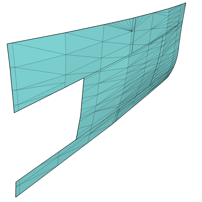
A quick look a Plate Section #2. Just a thumbnail .. you can click on it for a larger image. You can see the compound curve of this section. I have hidden lines showing just for the fun of it.

I am going to extrude this CAD four times along the Y-Axis and create three 0.5mm layers. The inner layer will simply be to hold everything together, the next two outer layers will hold the strakes with every other row proud by 0.5mm. In O scale this is ~1″ plate .. too thick but will be “good nuff” for the mechanical structure required for 3d printing.
I gave each panel a different color .. helps to keep you brain from falling out and splashing from cross-eyes. Each of these is on a separate layer .. for now.
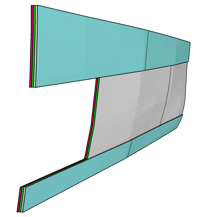
At this point we just have four shells. The blue shell will be the outermost strakes .. proud of the inner white strake by that 0.5mm. The next bit will be a bit time consuming .. but I am watching a video with chips, dip and beer so there’s that. I am going to add a vertical seam at each of the butts 0.1mm either side of the projected vertical line. This will give me a 0.2mm/0.008″ channel .. just enough to show up with panel liner. The time will be because these are compound curved panels.