")
Somewhere I acquired this old DC throttle control. I think it may have been stolen from Gary Wise. In any case when I remembered I had this I quickly decided to use it to power the DC side of my switching box. Taking it apart took using a Dremel tool to slice a slot in the center of a flathead screwdriver so it could remove the spanner screws that held the case together.
When I do a search for this item I get photos of the same case but with a large black control knob. I don’t know if this is a very old version or if someone has replaced the knob at some point.
")
With the case removed the transformer at the top right has two red wires to the circuit board, the power transistor mounted to the heatsink, on the right is the on/off slide switch and bottom center the red and black wires lead to the LED. At the top are the terminals for DC and AC. How much of the case I will re-use is for now anyone’s guess .. but probably .. most of it. I will want to re-locate the switches most likely (the direction slide switch is soldered to the PCB).
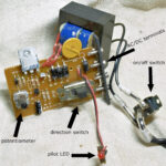
Some of the parts will be easy to re-locate such as the on/off switch and the LED. The potentiometer and the direction switch are soldered to the PCB so that’s more of a chore. The AC/DC terminals are on a board that is also soldered to the PCB. Let’s just say .. let that go for the moment and come back to look at this after I work on the new panel.
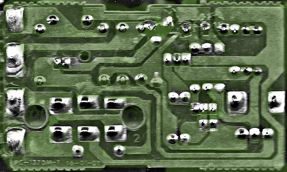
The PCB. I have to say I was a bit disappointed at the quality of the soldering. Looks like something a drunken Russian would solder up.
Ok. It works so .. there’s that .. just ugly as hell. I scanned the thing .. this is a false color image as it scanned like crap but .. yeah .. ugly.
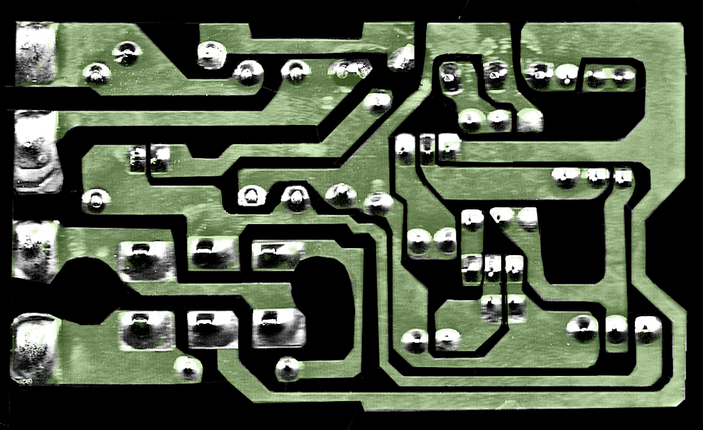
Here, I cleaned it up looking at what the traces were supposed to be and where they were not. This gives a much better idea of what is what and where is where .. and just saying less confusing.
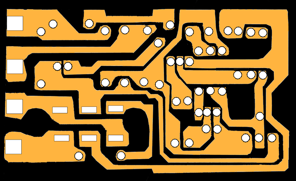
Finally, I created this from the last image. I can now put in the components if necessary. If I decide to replace the LED for example I want to know what resistor was used so I can figure out what current etc. Knowing what pin from the switches is used for what on the traces, how the pot is connected to will possibly help if I decide to move them.
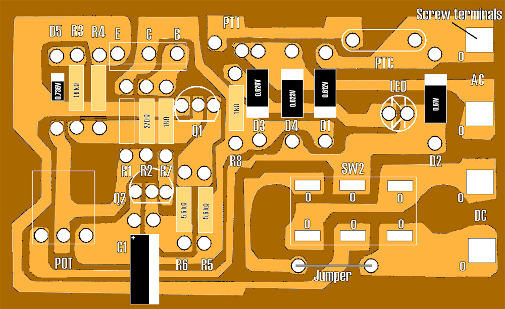
I mirrored the PCB to correctly appear as “see through” on the component side of the PCB. I amused myself by putting in the values for the resistors and diodes. I am only really concerned with the LED if I had to replace it at some point.