When you build a model kit of a car, plane, tank or ship one thing common are alignment tabs, pins, holes and such that allow the parts to fit together properly. I was attempting to this with my steam engine and had some issues.
When 3d printing there are issues with the parts not exactly matching the CAD drawing. Two main issues is the resolution of the printer and shrinkage of the resin from curing. The lower the resolution the more pixilated an image .. we see this on older computer games. The same thing applies to 3d printing whether a filament printer where the resolution is determined by the extruder nozzle or a resin printer where the resolution is dictated by the screen resolution of the LCD screen.

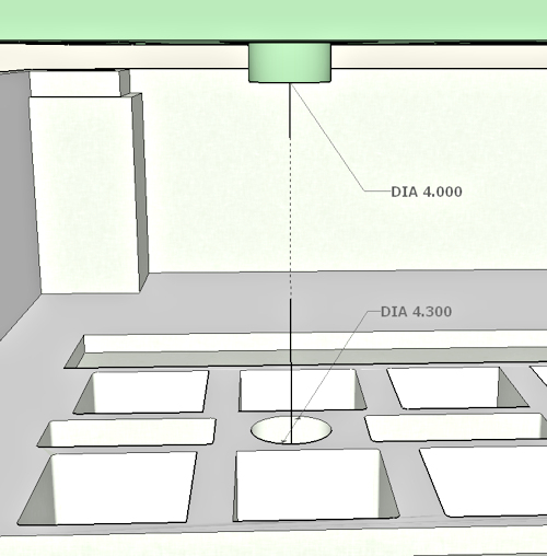
In this CAD drawing we have an alignment pin in green projecting from the bottom of the Engine bed. In yellow the matching alignment hole in the Engine room floor. I made the hole .3 mm larger than the pin. In a perfect world the pin should slide into the hole. This isn’t a perfect world though. The Engine is printed on my resin printer (Prusa SL1S) and the Engine room floor in PLA (Prusa i3 MK3S). From printing these parts and having problems with the fit I have some points:
- Generally I have shrinkage with both the PLA and Resin. Just how much depends on who knows .. the material, brand, ambient temperature . . shrug. If I am printing from same machine and material then that .3mm should allow the parts to slide together. With this though using two different printers and two different materials ….
- I chose the 4mm dia. for the pin simply as it fit in the area. I have come to realized that was a mistake. If I “assume” that both the PLA and the resin are going to shrink a bit and I am not certain how much then it makes more sense to print a part .. THEN .. ream the undersize hole with a drill bit. Don’t bother printing the pin .. if I am reaming a hole to a standard size then print/ream a hole for the pin and simply glue in the pin after to fit the hole.

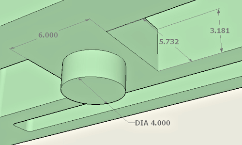
Here’s looking at the area where I put that 4mm pin. I made a base for the pin 6mm square and 3.181 high. At the time a 4mm pin seemed reasonable.
From what I said earlier then printing a 4mm hole, reaming to size afterwards with a 4mm drill bit and then inserting a 4mm pin would make sense. The problem with that is I only have a small selection of metric drill bits from Harbor Freight .. .5mm – 3mm, and don’t have a 4mm pin to play with, so I will stay with imperial which I have both drill bits and various pins/rods/tubing.
4mm is 0.1575″. That is just under 3/16″ .. a quick look in my box of Evergreen tubing and I found a length of No. 226 3/16 tube.

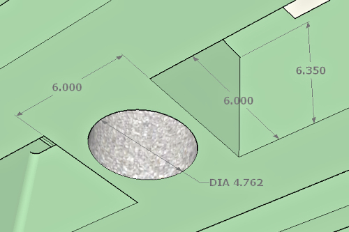
Here I removed the 4mm pin, punched a 3/16″ hole through the boss and increased it to 1/4″ thick so the tubing would have something to glue to. Now, when I print this part I will assume that it will shrink slightly (on the Elegoo site that the resin has 7% shrinkage) … so I will ream with a 3/16″ drill bit and then glue in the 3/16″ tubing.

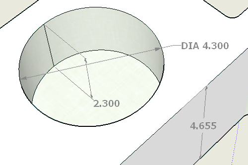
Now, looking at the Engine room floor. Here I had a blind hole 4.3mm dia. and 2.3mm deep. The depth is simply that I made the pin 2mm long. Now, I am changing the hold dia. to 3/16″ (4.762mm) and punching through the 4.655mm floor thickness as I will be using a 3/16″ drill bit to ream the PLA print.
While not directly related to the studs and holes I am talking about here, the plan is to use strips of magnetic tape to attach the engine to the engine room floor. I created a well in the engine room floor that is twice the thickness of the tape. One strip will glue to the bottom of the engine and magnetically attach to another strip glued to the bottom of the well. The tape measures 0.050″/1.27mm thick. Doubling this gives me a well depth of 0.1″/2.54mm. PLA has a shrinkage of in the range of 0.3% to 3% so that 2.54mm well depth would be 2.46mm at 3% .. or 0.09mm shallow .. or .. about 0.004″. Just to be sure I will “bump” that depth to 0.104″/2.642mm … probably not necessary but I would rather the well be a bit deeper than too shallow.
The Engine room walls are pierced six places … two by the crankshaft (1/8″ rod), two intake pipes from boiler to engine, condenser output to boiler and cooling water exit .. all 1/8″. I will print at 1/8″ and ream with a drill bit.
Thoughts:
I have heard it said that the difference between a beginner and an expert is that the expert has made all the mistakes and simply does not repeat them. I think that the “not repeating them” bit is something I need to focus on.

Perhaps you should add a chamfer to both male and female mating surfaces.
That idea is one of those “makes sense” kind of thing.