I-Beams
My original design for the Engine Room Skylight was about half the length it is currently. With that smaller footprint I had a superstructure consisting of the wheelhouse and a pair of lifeboats over the top of the Engine Room, supported at both ends by more superstructure flanking the Engine Room fore and aft.
With this redesign I completely forgot that I would have a long center section lacking the support needed. The port side of the Engine Room is tight with equipment so my first idea of simple support columns similar to those planned at the ends of the overhead structure might not work. I then thought of squeezing in some I-Beams in the Engine Room with a transverse beam straddling all the bits and bobs with a vertical support then extending up.
I had an I-Beam I had created for something else using Evergreen # No. 291 angle and 0.010″ sheet styrene. The I-Beam makes up to a beam height of 7.9mm and flange width of 3.3mm. That translates to a full-size I-Beam with a 14.93″ beam height and 5.9″ flange width.
I found an I-Beam (S15 x 50) that measures 15″ height x 5.64″ width … with a 0.55″ web thickness and 0.662″ flange thickness certainly close enough for modeling. Reducing those numbers down to 1:48 is interesting.

Here are three versions of the ~ same size I-Beams. On the left is one made up using Evergreen No 291 Angle and 0.010″ Styrene. In the middle is a standard S15 x 50 steel I-Beam. On the right is one I took from an Engineering math problem showing an I-Beam fabricated from angles and sheet steel bolted together.
What I found interesting is that if the edges of the Evergreen angle were rounded off the shape would be really close to the fabricated I-Beam.
Angle Supports
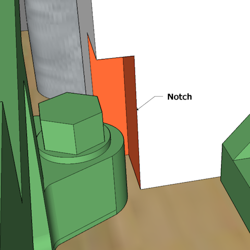
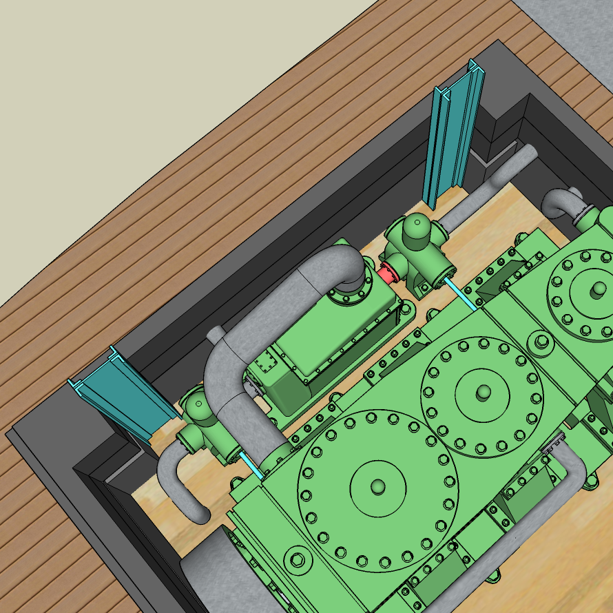
I looked really close and was able to “mostly” fit square column shapes that would align with the column supports outside the Engine Room. If I ignore that I need to move one of the engine mounts slightly .. which I can since this is a model … and you would not be able to see this in any case, I can simply “Carry On!”.
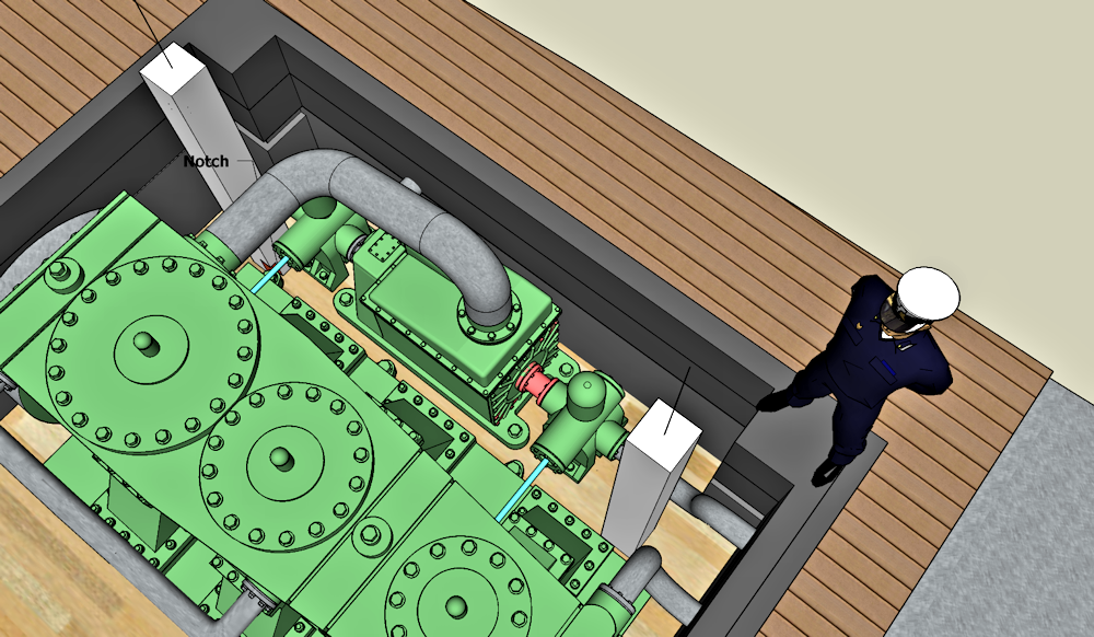
Like I said .. very cramped in the Engine Room but here is a look at the space I have for two square columns.
This is the “space” I have for a couple of support columns .. not the columns themselves. This was built c. 1880 so such column would have been fabricated from structural steel. I like using angles .. probably iron at this time .. again I can ignore all that and simply focus on the design.
I found “Speedy Metals® – Online Industrial Metal Supply with dimensions for 5″ Angle. Sweet! This shows that the 5″ angle has 0.5″ thick walls.