Post something. Okie Dokie. I don’t think I have posted in a couple of months. Heck … I haven’t done any modeling in that time .. CAD or otherwise. When I left off I was working on the Engine Room Superstructure .. and at the point of fitting said superstructure to the 3d printed Wedge that is the top of the Engine Room.

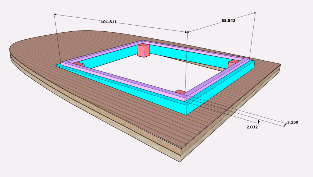
Here we have the Wedge. The bit shown in Cyan and Red are all the same 3d print … they are colored simply for identification; the purple bit slips inside the wooden laser cut Engine Room Superstructure and glues to the wedge bit ..
Cyan/Blue: This wedge fits to the Sheer Curve of the deck and a horizontal bit that forms the base for the Engine Room Superstructure.
Purple: (Alignment block) Fits the inside of the Engine Room Superstructure.
Red: Each of these is the pocket for REM (Rare Earth Magnets) .. used to “snap” this Wedge to the Engine Room Bottom.
The dimensions shown are from the CAD but give us what we need for the Engine Room Structure

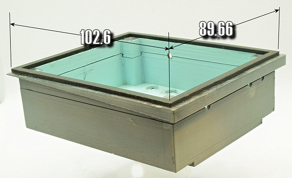
The Print vrs CAD
Most of the time it doesn’t matter if the print is slightly off-size … problems arise when you are fitting two prints together .. or something like.
The print is almost exactly 0.4mm wider per side. That is 1/64″ | 0.016″.
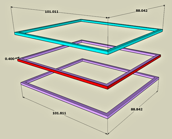
What this means is simply to reduce that Purple Bit by 0.4mm … and everything will be sooper doooper cool. (and me wondering how well that bit (purple/alignment block) is bonded to the wedge)
Pause .. at this point I am stopping to open up Sketchup and make those 0.4mm adjustments

I actually thought about re-sizing the Engine Room Superstructure .. and then realized that … * duh * .. I only needed to size the purple bit
I simply removed 0.4mm from all four sides of the Alignment block. The numbers shown are CAD .. anything past .1mm is suspect.
I need something to align this “alignment black” to the wedge.
