V2 is to the left. My attention kept being draw to the flat roof surrounding the skylight. I got to thinking that a boat might well have that part curved or slated to drain off water.
.. perhaps even worse V2 just looks … boring. Like I said .. I had issues with how it fit to the base .. and I had forgotten to allow for the 0.016″ Laserboard that I will be overlaying the walls with. So .. re-work the wedge base while I am at it.

V3. I changed the sides from a flat vertical wall to a set of sponsons. The roof slope matches that of the skylight. I had to resize almost everything to account for the thickness of the 0.016″ Laserboard overlays.

V4. Previously in V3 I had the Skylight as a separate piece. It occurred to me that this was introducing a lot of wasted time and effort in that I had to create a shoulder for the Skylight to sit on and that in “real life” it would be much simpler to merge everything.
Funny but at some point I thought about creating scenes in Sketchup to show the virtual build. This turned out to be a blessing in disguise as I was virtually assembling the thing I kept finding mistakes in the CAD. The ability to click on a scene and then show and hide elements made the effort for finding and fixing errors a lot easier.
Here’s the virtual build Animation created from those scenes – Video
")
V5. The outside looks the same but I realized that the roof supports I had originally designed for the sloped sponsons were unneeded so deleted those which affected the walls of the skylight and sponsons – meaning I deleted the slots I had for the sponson supports. I changed the gables from flat walls to beams (~ 3″x6″) that look much better IMO as the skylight rafters.
")
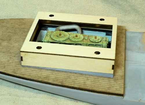
I used rare 5x3mm earth magnets to allow disassembly while holding everything together.
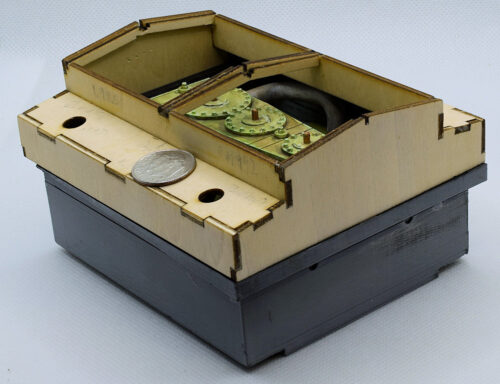
Finished all of the main structure and 3d printing. Ready for the Laserboard overlays.
You may wonder why I have gone into all this detail. I was curious as to how well I could make this in O scale .. make it detailed in steps .. logical steps. Interlocking bits such as those forming the cabin .. learn new techniques and procedures.
One of the things is to make better use of jigs. When I was gluing the walls together I used various clamps and magnetic 90° clamps to hold the parts. I have since realized that I could do this much better using 3d printed jigs that would precisely locate everything .. basically .. “Note to Self”.
")
I learned quite a bit coming up with the design of the Laserboard. I used Sketchup for the CAD and exported the DXF file which I can directly import into Lightburn. One problem I have is using colors in Sketchup that will match the layer colors in Lightburn. The other problem is that the etching was too strong .. to Lightburn the difference between etching a line and cutting is simply power and speed.
I cut some more Laserboard with Cut: Speed/Pwr 10/50 and Etch: Speed/Pwr 25/30 and had good results.

looks good