Version 1
The quarterdeck is a raised deck behind the main mast of a sailing ship. Traditionally it was where the captain commanded his vessel and where the ship’s colors were kept. Wikipedia
I am using this term to refer to a raised area on the stern of the Grazyna. The purpose of this is two fold .. one to give more depth to the area as this is shallow this being a waterline model and more importantly give a place to attach the bulwarks to.

When I started this project years ago I started by making bulkheads from drawings showing hull lines and sheer plan. From this I made the bulkheads and keel and then filled in the spaces with balsa and expanding foam and sheet basswood. I only wanted a boat shaped water line object that I could later plate and/or plank as needed as this was just for a static display.
The problem later on is that this was/is very much organic in shape which means that trying later to add the quarter deck poses some difficulty.
Coming back later and trying to fit the raised stern deck/quarter deck to fit that organic shape takes time and some of the planning that I failed to do previously.
")
Tracing, Scanning and CAD: I traced the top of the boat onto cardboard, which I then scanned, brought into my graphic program where I took half of, mirrored to get the same shape on both sides, brought into Sketchup where I traced the outline. Created a DXF file that I imported into Lightburn and laser cut the quarterdeck. The results was oversized .. but .. the hole for the Engine room allowed me to use the Engine Room print to lock the hull and rear deck piece together and then I could trace around the deck piece and sand to that penciled line.
This is where I am as I type this. The CAD I created previously were really only good enough to laser cut out the raised deck as I have now sanded it to the pencil line I used the hull shape to create. The original plan was to offset the raised deck the thickness of the bulwark as a gluing edge. I am basically where I started except .. “perhaps” I can use this “fitted” raised deck to scan and get a good CAD file. THEN .. mirror the sides etc., cut a new raised deck then GLUE that to the boat and use bondo to blend everything together and THEN I can use that file to create a new offset piece.

Take 2: Here’s the scan of the raised deck that I sanded to fit. While not crazily different, the sides are not exact mirrors of each other. The next step will be an attempt to fix that.
Not a bad scan … there is a bit of shadow cast but that is easily cleaned up in my graphics program.

Paint Shop Pro, Lightburn and Sketchup: I brought the scan into Paint Shop Pro and cleaned it up then made all of the scanned part black and the rest white. This was for import into Lightburn.
In Lightburn .. screen capture to the left … I used the trace function and exported as a .DXF file.
Now imported the DXF file into Sketchup where I split the image down the center, took the left side which seemed more correct and cleaned up any remaining glitches and then mirrored to make a whole graphic. I adjusted the width as needed .. there was a slight difference due to all the various scanning, exporting and importing done. This will be glued to the stern and I will use bondo to blend it into the stern. I then made a copy and offset that 0.010″/0.254 mm to make the bit I need to glue the bulwarks to. This means that I will add another 0.130″ to the deck height but .. shrug .. this is all made up anyway. I took that same offset drawing and made a copy with etched lines (6″ Full-size .. in 1:48 made them 0.125″) .. I can use this to etch the planking into some 1/16″ or even 1/32″ basswood.
Lessons Learned :
- If you submit a black and white graphic to Lightburn it can trace the outline nicely which you can then export as a DXF file. If I can figure out how to convert the png/jpg into a Vector graphic it would be better. When I did the trace and zoomed in you can see the little wiggles in the line as it was from a scan of a hand sanded object. Some way to have software convert to smooth lines would be cool .. something to look into.
- Sketchup will import the DXF file which allow easier manipulation .. for me at least. I am sure you could do the same in Lightburn .. I am just really familiar with Sketchup. You can export back to DXF then to load into Lightburn. It’s a hack to be sure but it works.
")
Gluing the raised stern deck down. I will let this set up .. find something else to do while the glue dries. I have a bad habit of rushing such.
")
Deck Stain: The other day I was looking at the raised rear deck and realized I had no clue what I stained the overlay with. Then, today I found this photo.
Version 2

Margin Plank – and more – I was working on the Grazyna and thinking about planking the main deck similar to the way I did the quarterdeck. It was a major pain to do that though since I was trying to fit what was basically a hand built deck … which was/is mostly, kinda sorta almost the same on both sides of the centerline .. which is a PITA. I then realized that I had the planking running all the way to the gunnels .. and that what actually happens is that the planking runs to what is called variously a margin plank, perimeter board, nibbing strake etc. so that the tapered ends of the planks to prevent sharp points. I hadn’t done that .. and .. I wanted to add that detail. That made me think that I might instead 3D print the hull. Then I would have exact dimensions as needed, I could add the deck camber. I could 3d print the plating complete with rivets. I could add the needed bits and bobs to more easily include bulwarks etc.
In this drawing the planks are in green and the margin plank in blue. The planks are “nibbed” into the margin plank. The circles are wooden plugs that cover up the bolt heads.
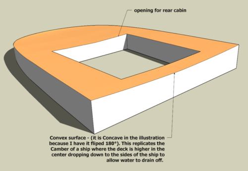
Camber – The deck of the ship is not flat but Convex On a ship this is the camber where the center of the deck is higher than the sides to allow water to run off. A general rule is that the center of the deck measuring transversely is 1:50 the breadth. I designed this into my 3d model but I have a question as to gluing the 0.015″ laserboard I will be using to etch the planking and margin planks since it is flat and the camber of the deck is therefore convex. I am testing this by printing a mold .. upper and lower – the same camber as the deck and to see if I can pre-curve the laserboard. My understanding is that laserboard is a paper product mixed with resin. It takes stain pretty well so it is at leas a bit hygroscopic. I may be able to soak it in water and then clamp between my the mold and pre-form it.
Note: One of my many failings is that I don’t plan ahead. I printed this upper/female mold with ironing selected .. completely forgetting that I was printing at 0.3mm layer height. I ended up with what looked like a series terraced rice paddies. Now, I am printing again this time with variable layer height so only the curved area (the tan colored bit) printed at a low layer height.
Note: I also enlarged the opening in the center (for the rear cabin insert) by 0.1mm per side. I test fitted the insert .. the engine room walls .. and while I could just barely push it into the opening it was very tight.
")
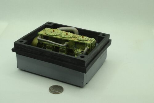
Engine Room Insert – This forms the walls of the engine room, the engine and supports framing. This will only be seen through the skylight so the slight warping of the framing will not be visible. The round silver objects in the corners are Rare Earth Magnets which lock to magnets installed in the upper or top of the engine room to allow access as needed.
The dimensions as shown are those that I had to modify the opening of the hull to provide clearance. I added -.1mm to all sides. The CAD dimensions of that opening are 99.2mm x 86.12mm .. are ~ 0.2mm per side larger but this allows for a bit of shrinkage during printing .. measurement of the test print with an added 0.1mm per side was used to get these dimensions.
If the hull were perfectly flat then this would simply slide into the deck opening then that would be that .. .simple. The deck isn’t flat. From bow to stern it curves higher at the ends and lower in the center. This is called the sheer.
Sheer is the upward curvature of a ship’s deck from amidships toward the bow and stern, primarily designed to improve seaworthiness by raising the deck height. It increases reserve buoyancy at the ends, preventing the bow from diving into waves (pitching), reduces the amount of green water shipped on deck, and provides aesthetic appeal.
Then there is camber. Camber in ship construction is the transverse (athwartships) curvature of a deck, where the centerline is higher than the sides, designed primarily to facilitate water drainage, enhance structural strength, and assist in fabrication. This rounded, parabolic shape (or “round of beam”) prevents water accumulation on exposed decks and improves resistance to longitudinal bending loads.
What this means for me is that I have the sheer which curves the deck upward from the center and curves transversely from the center to the sides. To account for that the upper section of the Engine Room Insert needs to match this compound curving. This also gives a level surface to mount the rear cabin / Engine room superstructure.
Engine Room and Wedge Assembly – This is what I am calling the Engine Room + the Wedge. This admittedly took a while to create. I use Sketchup so not as easy to intersect curves with shapes but with a lot of manual work “got her done!”. I’m sure that more advanced CAD software would have allowed joining the compound deck curves .. camber and sheer .. with the vertical wedge section but I paid for the 2016 Sketchup Pro software and have little desire to change programs unless this one stops working. The “don’t fix it if it ain’t broken” comes to mind. The engine room was already built and I had no desire to recreate it. I did remove the support framework as it was interfering with the new wedge assembly .. and I realized it could not be seen through the skylight anyway so why keep it.
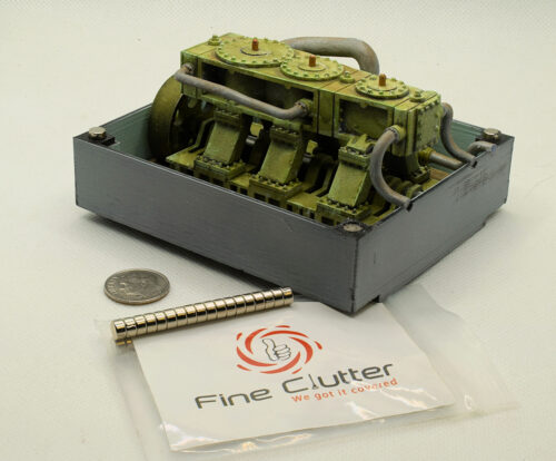
Matching Engine Room Magnets – The wedge assembly snaps over the Engine Room and is held in place by 5×3 mm Rare Earth Magnets from Amazon. The ones glued in place can be seen in the photo where I dropped a couple of loose magnets on top of them. They immediately flip to align positive to negative .. I then simply need to glue into the bottom of the Wedge Assembly, keeping them aligned in this same position.
Note: Getting the orientation wrong means they will push against each other. There are no markings on the magnets. It would be easier if there was a small S or N engraved on them. These are advertised as “Refrigerator Magnets” so normally this would not matter. I have some United Scientific™ Alnico Bar Magnets that makes it easy to determine polarity identification and then using a engraver to mark them … or …. just be careful when gluing them in the wedge assembly in this case.