Let me start by saying that I am basically clueless abut steam engines. I now just enough to get myself in trouble.

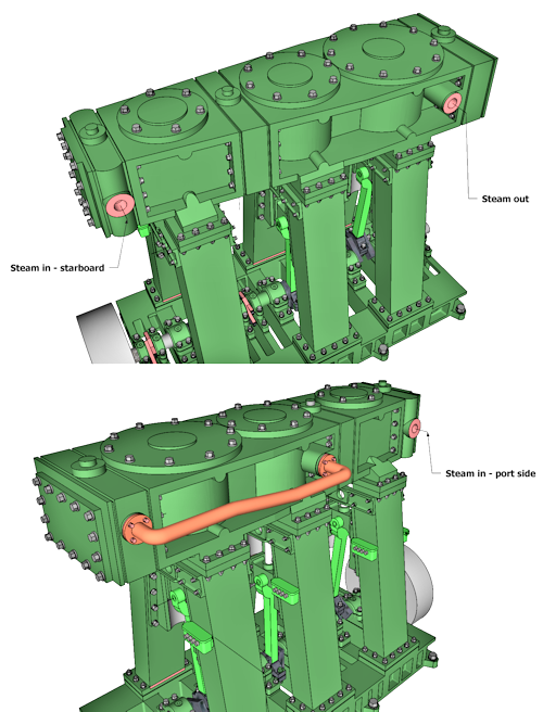
Front of engine – I am calling this the front of the engine since it is the opposite end of the flywheel. I added a flywheel as a space holder simply so my tired brain would have an easier time seeing which end of the engine was the front and back.
In the drawing I have labeled the parts I have “discovered” to this point; the locations of the slide valves and cylinders. Steam in to the HP slide valve block (High Pressure) … there is an identical “Steam in” on the opposite side of the engine … the port side (my “assumption” is that perhaps two boilers feed the HP Cyl.). I have a pipe from the LP (Low pressure) slide valve block to the IP (Intermediate pressure) slide valve block. This is all from a drawing of a model steam engine as it is well labeled (Triple Expansion Compound Engine – By Julius de Waal).
Sheet 1: “The original drawing shows the exhaust steam is piped into a condenser, also a condenser pump is shown.“
For this engine we have the one pipe from the LP cyl. (low pressure) to the IP cyl.(intermediate pressure). The steam is transferred internally between the IP cyl. and the HP (High pressure) cyl.
There are two steam-in locations on either side of the HP cyl. and a steam-out between the LP cyl. and the LP Stephenson valve block. This is what hooks to the condenser and condenser pump.
Port size: “In steam engines, the size of the steam ports (the openings that allow steam to enter and exit the cylinder) is crucial for efficient power delivery. A common guideline is to make the port area approximately 1/100th of the piston area when the piston speed is about 60 feet per minute during the part of the stroke where the valve is open. The exhaust port should be at least twice the size of the steam ports, measured fore and aft, according to IBLS.” – AI Overview
Example: “If a piston has an area of 100 square inches and the piston speed is around 60 FPM, the total steam port area would be approximately 1 square inch, according to The Steamboating Forum. The exhaust port would then be at least 2 square inches.” – The Steamboating Forum

Maths: This model was influenced a lot by the Triple Expansion Compound Engine by Julius de Wall .. mostly because of the detailed drawings.
Some Details:
HP Cyl. Bore = 33 mm
IP Cyl. Bore = 48 mm
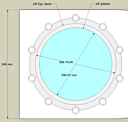
LP Cyl. Bore = 67 mm
From the plans showing the LP cyl. I get two needed dimensions … the width of the High Pressure Block at 100 mm (W) and the bore at 74.45 mm (B). From my model dimension W is 11.967 mm / 0.47″. This is a 1:48 model so full-size this would be 22.56″. The B dimension for my model therefore using a “Handy Dandy” Proportional Calculator because I am lazy) …
100/11.967 ~ 74.45/x … or … 100X = 890.94315 .. solving for x … X = 8.9 (and change).

So. A bore 8.9 mm dia. has a area of 62.21139 sq.mm. If the total steam port area is 1/100th of the piston/bore area then the port needs to be 0.622 mm .. or a pipe 1.24 mm dia. The exhaust port twice that at 2.48 mm dia.
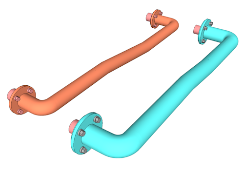
The pipe I have at this point on my model has a 0.98 mm dia. .. a bit undersized (orange pipe). The re-calculated pipe is in blue.
