Note: This is not in any way a realistic guide to this subject but instead notes for making a 3d print in 1:48 that gives the appearance of being correct while will print successfully.

Lubing the bearings: The question came up as to how I was going to lube the bearings on this steam engine. In my world it was created c.1880 (ish) so that meant these would have been “plain bearings” also known as journal or friction bearings mad from a soft, non-ferrous alloy like Babbitt metal. Early on these were lubricated by constant application of oil from oil reservoirs located above the bearings. Later on they were fed from an automatic lubricator.
For my model a revivor for the oil is moved to a mount to the main strut with pipe to the individual bearings. This is just a “visual thing” .. I will for now ignore lubing the cylinders etc. … assuming these are “out of sight”
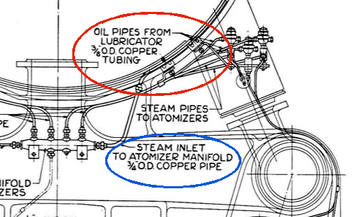
The drawing above is from a steam locomotive where it specifically states that they use 3/8″ O.D. Copper tubing (circled in red). On aside note, 3/4″ O.D. Copper tubing was used to feed the Atomizer Manifold.
1:48 – O scale :
0.375 / 48 = 0.0078~ … or .. call it 0.008″ / ~0.2 mm
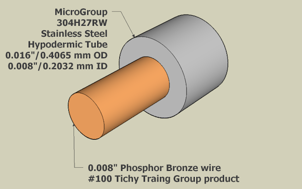
AWG 32 wire happens to be 0.008″ dia. – which you can purchase at Amazon.com. but … “cool beans” … I have 0.008″ Phosphor Bronze Wire, #1100 from Tichy Train Group. Perfect!
One of the problems with 3D printing small objects is there is a limit on how small for the wall thickness. You can print a wall 0.1 mm thick but it will not hold up … it is simply too weak. A 0.3mm wall thickness IMO is the minimum .. and 0.4mm better. That means the minimum size of a boss around a wire would be 0.6mm larger diameter over the wire diameter. That AWG 32 wire at 0.008″ / 0.2 mm diameter would be 0.2 mm + 0.6 mm or 0.8 mm diameter. The smaller the wire the move obvious how overscale it is.
Another problem is that resin shrinks when curing. The smaller the hole the more that shrinkage will cause problems. Generally … I think that printing the hole 125% larger will give you a hole that is close to the size wanted … worse case can be easily reamed to size with a drill-bit. I could add “another problem” being that the resin is brittle and drilling holes is chancy.
In this case a 0.2 mm hole enlarged b 125% would be 0.25 mm. Adding a 0.3 mm wall around hole would mean a boss 0.825 mm dia. To make that make sense .. in 1:48 that 0.2mm / 0.008″ wire would be 0.384″ … ~ 3/8″. The boss around it would be 3-1/4″ … nasty visually.

Enter Micro Tubing: Since the reason for a boss where the wire enters the bearing cap is to represent a fitting I need something else. A vertical face with a minimum .3 mm from the wire to the edge would work … but what to use to replicate the fitting?
I can buy Hypodermic Tubing made from stainless steel that has a nominal ID of 0.008″ and a nominal OD of 0.016″. This would make a “fitting” ~ 3/4″ .. much, much better. Enlarging the CAD dimension by 125% means I need to design using a 0.5 mm hole.
Fooling the eye: What I want is for a reservoir mounted on the main strut with copper tubing running from that to each individual main bearing cap and the throw caps. That isn’t as simple as just poking a hole somewhere. Putting a hole mean that the 0.3 mm wall thickness needs to be taken into account.

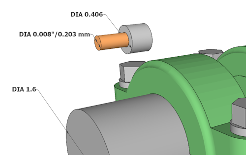
Here I have the bearing cap with the Stephenson Linkage throw. Floating above it is the 0.008″ Tichy wire and a bit of the MicroGroup 0.016″ tubing to represent 3/8″ brass tubing and a fitting. Keep in mind that the bearing cap you can see is what I am calling the “short bearing cap” … it and the one on the far side are for bearings that support a throw for the Stephenson Link that operate the valves.
The width of this bearing cap is only 0.8 mm in width … ~ 1.5″ in 1:48 … or … about 1/32″ in width actual size. I only point that out to show how ridiculous this is .. I’m just having a great time seeing how I can replicate something like this in scale.

Location, location: The question is .. where to locate the wire and tubing? Wherever I place the wire vertically against the bearing cap I need that .3 mm minimum wall thickness above the wire if I want a hole for it, or ~ .4 mm above the wire.
If I just glue both the wire and tubing flat against a face of the bearing cap then I only need a bit above the tubing .. say .. .1 mm. So .. from center of the wire to the top of the tubing + .1mm = .1 + .2 + .1 = .4 mm. If I center the wire on the top of the bearing cap than I need a boss .4 mm tall .. a bit under 3/4″ full-scale. I will just let that trail off. I wanted to have the wire (the copper tubing) to come out from the bearing cap horizontally but that requires a lot of back flips and … not really worth the trouble.
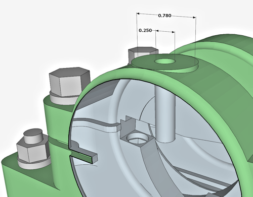
Makes much more sense to come vertically from the bearing cap as there is just barely enough “meat” for that. The “tubing” then then bend 90° to run to the oil reservoir. Here, the “meat” around the hole (125% oversized) is slightly under that 0.3 mm I talked about but only slightly and the wire will be glued in so should be fine. The hole as you can see in section view looks deep but in reality is only 1 mm deep.
On a side note, the reason the boss is 0.78 mm with the bearing width there 0.8 mm is that it simplifies the CAD a lot with just two tubes intersecting.
