Since my plan is just to see the top of the engine through the skylight my question is simply .. how large does it need to be? Don’t take any of the seriously. I am just having fun.
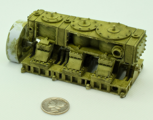
Dimensions: I made the length of the engine 3.124″ (12-1/2 ft. long full-size). The Liberty Ship engine I am using as a guide was 21 ft. long and 19 ft. tall .. so proportionally that would be 3.124″/79.34 mm long x 2.83″/71.88 mm tall (12.5 ft. long x 11.32 ft. tall full-size) Since I will be foreshortening the engine height as this is a waterline model, that means little due to the foreshortening. That length is longer due to adding a flywheel. The length over the ends of the driveshaft ended up at 3.760″. This is the inside length of the Engine Room. The printed Engine Room will have walls 1/16″ thick, so the long side of the opening needs to be 3.760″ + 1/8″ = 3.885″. The width of the opening is 3.375″. Subtract the two 1/16″ walls and the inside width of the Engine Room is 3.25″.
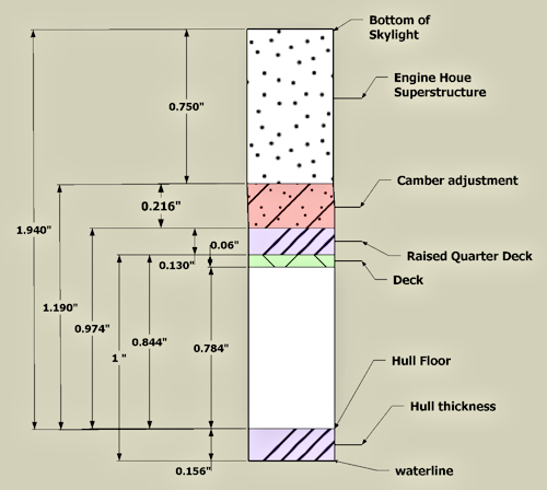
Following I get a bit pedantic .. but this is my way to get a handle on measurements. The bottom of this waterline boat gives me a reference point. There is a rectangular hole I cut through the deck to the top of the 5/32″ thick bottom – calling it the hull floor. It is easy using my dial calipers to measure from the center of the deck to that surface. The measurement of this distance at the front and back of the hole is different due to the sheer of the boat. This distance at the back of the hole edge (BH) at 0.965″. The front hole edge (FH) is 0.780″. I will print the Engine Room at some point to form the walls and bottom .. but I need to have the engine fit within which then determines the final location of the FH due to adjustment due to the wall thickness of the Engine Room insert. This insert will also account for the camber produced by the sheer.
Note that the drawing below was created using the original shorter opening in the deck and will probably change as I develop this.

Deck to Hull Floor and camber
- From the deck(BH) to the hull floor is 0.965″.
- From the deck (FH) to the bottom of the hole is 0.784″.
- A raised Quarterdeck will be added from 0.130″ plywood, offset to have a surface to glue the bulwarks to.
- FH is 0.965″ – 0.784 = 0.181″ lower than BH due to the sheer of the boat.
- The Raised quarter deck will be 0.130″ thick so from (BH) in the Raised quarter deck to the hull floor will be 0.965″ + 0.130″ or 1.095″.
- The Raised quarter deck will be 0.130″ thick so from (FH) in the Raised quarter deck to the hull floor will be 0.784″ + 0.130″ or 0.914″.
Engine Room
- The Engine Room is a printed insert that slips into the opening held in place by shoulders that act as the camber adjustment. The outside dimensions are 3.315″ W x 3.886″ L to fit the deck opening. Inside dimensions are 3.25″ W x 3.760″ L (1/16″ walls).
- From the section at FH we have 0.974″ from the underside of the shoulders to the hull floor. Figure 1/32″ to clear that floor and the number changes to 0.974″ – 0.032 = 0.942″. I want a 1/16″ floor thickness so now the number is 0.942″ – 0.063″ = 0.879″. This is the wall height then.
- My Engine Room consists of the Engine Room superstructure ~3/4″ tall The skylight sits on this so I’m thinking the top of the engine is at maximum to the bottom of the skylight/top of the superstructure. This would be the 1.028″ + .75″ = 1.778″. This is an important number as it sets the maximum Engine height after foreshortening. I would think that cutting about 3/8″ off that would make sense ~ 1.4″
- The maximum length of my engine needs to be .. give it a 1/8″ clearance so call it 3.125″ long (12.5 ft. full-size).
- From a drawing of the ship there is approximately 1.6 inches from the waterline to the keel. If I simply say that half of that is useable space for the engine then that would be .8 inches or adding to the waterline measurement 1.285 + .8 = 2.085 .. or ~2″ to the theoretical bottom of the engine.
Liberty Ship Engine
Liberty ship engines. 21 ft long, 19 ft tall developing 2,500 H.P. – Power (in horsepower) = (Mean Effective Pressure) * (Area of Piston) * (Piston Speed) / 33,000. Since I am changing the volume of the engine .. which affects the area of the piston then I can just use volume ratio to get H.P.
Liberty Ship Engine Flywheel: The flywheel on a Liberty ship’s triple-expansion steam engine was a significant component, typically with a diameter of 12 feet. From calculations below “my” engine has a scale factor of .6 from the liberty. Proportionally then it would have a 7.2 foot diameter flywheel. It is way more complicated then that as a scale factor of .5 would be 1/8 the volume/mass of the Liberty engine. In the end .. a flywheel .6 x .6 x .6 = 0.216 the volume. If that 12 ft diameter flywheel had a 1 foot wide rim then it would have a volume of 113.1 cu.ft. .. so a flywheel 7.2 feet in dia would need to be 2.8 feet wide. Sounds good .. “good nuff” for my model at least.
From a drawing of the ship there is approximately 1.6 inches from the waterline to the keel. If I simply say that half of that is useable space for the engine then that would be .8 inches or adding to the waterline measurement 1.285 + .8 = 2.085 .. or ~2″ .. but .. again .. foreshortening so .. shrug.
Calculation for 1.41 inches / 35.8 PMM (This height proportional to the Liberty Engine’s
1.41 inches (O scale) = 67.7 inches / 5.64 feet
Scale Factor = 5.64 / 19 = .3
(.3^3)*2500 = 67.5 H.P.
Calculation for Version 2 engine. Ignore the height as it will be visually foreshortened. You only see the top of the engine and bits and bobs of the bottom of the struts and bed plate from above.
2.83 inches (O scale) = 135.84 inches / 11.32 feet
Scale Factor = 11.32 feet / 19 = 0.59
(.59^3)*2500 = 513 H.P.

5/16/2025
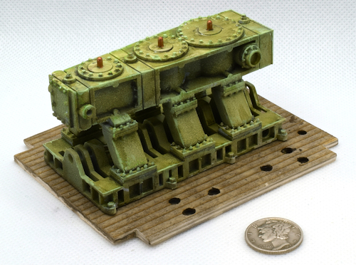
Version 2 of the engine. I used Tamiya white Fine Surface Primer and then brushed on two coats of vallejo Dark Green wash.
I didn’t want to obscure the details with thick paint and I am too lazy to use my airbrush. I thought the wash worked pretty well and I intend to follow up with OPR (Oil Paint Rendering) and a dark pin wash later on .. possibly dry brushing.

6/4/2025
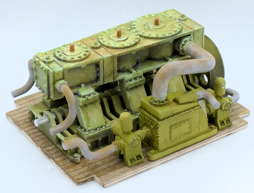
The engine is now up to version 5 .. hopefully the last one. The good thing is that I designed this so to some extent I can replace it at a later date if I need/want to.
It’s mounted to a base which is the Engine Room floor. There is a 2 mm plywood “subfloor” with laser card that has etched planks glued to it. The engine then is glued to the floor. The dark spots are holes for the accessory equipment .. aka .. locating pins and holes.

6/4/2025
Calling this “Good Nuff” .. I think I printed the pipes (steam in) at the front three times to get it right.
