Since I will have a skylight over the engine room to let in light I wanted something to be visible. I tried searching for overhead images of an Engine/Boiler room with no real success. I then thought that something “Engine Shaped” visible under the skylight might be better.
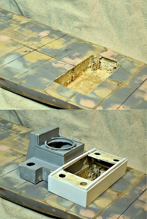
The engine etc. is another subject but for now let’s consider the room itself. With the skylight removed what I will have is a 1-3/4″x3-3/8″ hole in the deck under the skylight abut 1″ deep. I thought about gluing in styrene for walls and a floor but that seemed to me to possibly be a step toward insanity.
I have previously made a wedge shaped base to account for the Sheer of the ship .. and then I got to thinking that perhaps I could 3d print the Engine Room walls and floor. If I paint everything black then things like engines, boilers, pipes et. might look pretty good.
The top photo is a rough removal of material. When I made this hull I had no plan to “dig” into it and it is a mishmash of 1/8″ plywood, balsa and expanding foam.
The lower photo is the Engine Room superstructure placed over the hole for the photo op.
The hole is slightly undersized .. waiting for the 3d print of the Engine Room walls and floor so I can make the hole fit the print.
I published this page back on April 22 at which time the engine was designed to fit the small area I had carved out of the deck. Since then I doubled the size of the engine which meant I had to compress it vertically … the reasoning being that it would be viewed from the skylight so the foreshortening would not be obvious (necessary for the waterline boat). This means that the Engine room superstructure viewed above had to be tossed. I am currently printing V4 of both the Engine room insert and engine. Fun continues …

5/29/2025
I guess I may start adding the date to these entries. No real reason other then to perhaps mark the progress.
Enlarging the engine means that I scrapped the old styrene superstructure and need to build something new around what I have now.
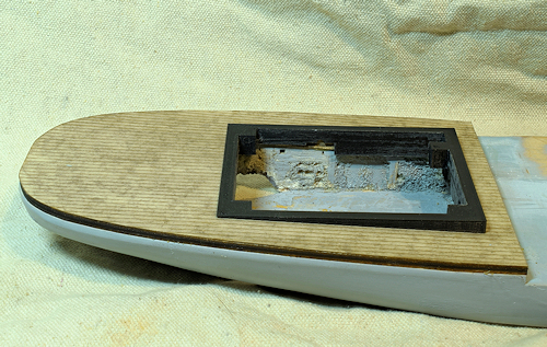
One of the problems I ran into is that when I built this boat it was all by hand. While visually the the thing is symmetrical .. it really isn’t. I needed it to be so as I want to add decking. This was not easy … I had to use cardboard to scribe around, scan that, bring into Sketchup so I could trace that pattern, split it down the center and mirror one side to get a symmetrical shape, a bunch of jumping around to get a file I could load into Lightburn, laser cut the rear deck, glue to the boat, fill in with Bondo and sand, add a second rear deck that was offset to the inside by 0.010″ so as to form a ledge for the bulwarks to glue to and finally laser cut laser card planking.
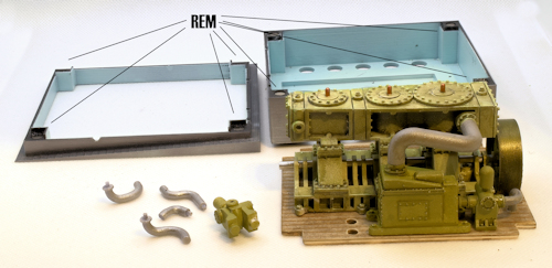
Because of the sheer of the deck I had to make a wedge shape filler to level out where I wanted the superstructure. That then evolved into adding walls and a floor to create the engine room. In the photo is the upper portion of this engine room print for a test fit and photo op. This Engine room print has a “wedge floor” and “wedge” .. upper and lower halves with holes for guide pins and the various piping. It has locations for small Rare Earth magnets to hold the pieces together as well as locations for Magnetic tape to hold the print whole to the boat and to the engine. The plan is the magnets secure everything while allowing easy disassembly.

6/3/2025
A look at where I left off last night. I was putting everything together when I couldn’t find the coupling that I KNOW that I already printed but .. it vanished. It goes between the pump and condenser (left side). In the photo the engine room is sitting behind the steam engine. To it’s left is the top of the engine room. There are REM (Rare Earth Magnets) used to hold these together. You can just see a long “well” beyond the engine .. that is where magnetic tape will go .. one piece glued down in the well and the other to the bottom of the wood floor. Lastly after gluing down pump/coupling I can attach the rest of the piping .. they glue to the engine/or/pump and condenser and the ends rest in “cups” you can just see .. top and bottom formed by the engine room halves. I am waiting for that before painting the pipes .. the “tin” color is just a base .. I will cover that with a wash of white, black and gray

6/4/2025
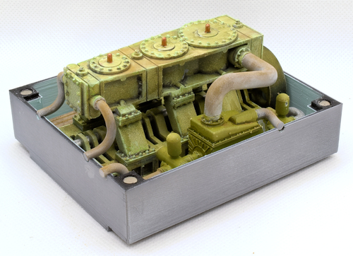
Assembled except for the upper part of the engine room. I had problems getting the two steam in pipes at the front .. printed them light three times until I finally remembered I had added the 0.016″ thick laser card floor and forget to account for that .. and then needed to add the wall thickness. The other pipes I had also not accounted for that floor thickness but managed to get the pipes to fit without having to reprint them too.
